Introduction
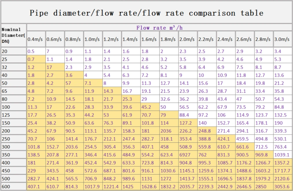
In fluid mechanics, the design of the pipeline is closely related to the efficiency of fluid transportation. To understand the relationship between pipeline diameter, flow rate, speed and pressure, some basic knowledge is usually required. The following content provides basic formulas, calculation processes, case analysis and Velocity selection suggestions for reference.
Basic Concepts
Flow Rate (Q): The volume of fluid passing through a pipe per unit time, typically measured in cubic meters per second (m³/s).
Velocity (v): The speed at which the fluid flows through the pipe, measured in meters per second (m/s).
Pipe Diameter (D): The internal diameter of the pipe, which influences fluid flow characteristics.
Pressure (P): The force exerted by the fluid within the pipe, which has an inverse relationship with velocity.
Fundamental Formulas
1. Relationship Between Flow Rate and Velocity
Q=A⋅v
Where the cross-sectional area A is given by: A=πD²/4
2. Bernoulli’s Equation
For ideal fluids, Bernoulli’s equation can be expressed as: P+½ρv²=constant
Where ρ is the fluid density.
Relationship between pipeline flow and pressure
The flow rate is not determined only by pressure: even if the pressure P in the pipeline is known, the flow rate cannot be directly calculated. The flow rate depends on the length of the pipeline and the pressure difference at both ends. The pressure in the pipeline is directly proportional to the flow rate. The higher the pressure, the greater the flow rate.
Calculation Process Example
Assume we have a pipe with an internal diameter of 0.1 meters and a flow rate of 0.01 m³/s. We will calculate the velocity and pressure changes.
Calculate Cross-Sectional Area (A): A=π(0.1)²/4=π×0.01/4≈0.00785 m²
Calculate Velocity (v): v=Q/A=0.01/0.00785≈1.27 m/s
Pressure Calculation:
Assume the fluid density ρ=1000 kg/m³ and use Bernoulli’s equation: P1+½×1000×(0)²=P2+½×1000×(1.27)². Assuming initial pressure P1=200000 Pa: 200000=P2+½×1000×1.6129. P2=200000−806.45≈199193.55 Pa.
Calculate Pipe Friction Factor (S):
Use Shevelev’s formula: s=0.001736/d^5.3 or s=10.3n2/d^5.3, or find related forms.
Determine Head Difference (H):
Formula: H=P/(pg)
If there is a horizontal drop h (the beginning of the pipe is h higher than the end), then H=P/(ρg)+h
Where P is the pressure difference at both ends of the pipe, and h is the horizontal drop. Where: H: in m; P: is the pressure difference at both ends of the pipe (not the pressure of a certain section), in Pa.
Recommendations for Velocity Selection
Velocity Range: Typically, the velocity within a pipe should be maintained between 1 m/s and 3 m/s to ensure stable flow and minimize energy losses.
Consider Fluid Characteristics: For fluids with higher viscosity, it is advisable to select a lower velocity to reduce pumping energy and pipe wear.
Avoid Water Hammer: When transporting liquids, excessively high velocities may cause water hammer effects, which can damage pipes; thus, maintaining an appropriate velocity is essential.
Conclusion
The relationship between pipe diameter, flow rate, velocity, and pressure is a fundamental topic in fluid mechanics. Through proper calculations and analysis, pipe design can be optimized, enhancing fluid transport efficiency. In practical applications, selecting the appropriate velocity is crucial for the safety and economic viability of the system. Both qualitative and quantitative analyses play vital roles in understanding and optimizing fluid flow in piping systems.
If you have any questions, please contact us directly and we will reach you soon.

